External RAM memories in MCS51 architecture (8051/8052)
This article also applies for microcontrollers that are 8052 derivatives (for example, AT89C52, AT89S52, AT89S8253, among others more modern ones)
When an external memory position is read (movx a, @dptr), the microcontroller does the following steps:
- P0 = DPL
- Pulses ALE pin
- P2 = DPH
- Pulses P3_7 (RD) pin
- A = P0
When writing to external memory (movx @dptr, a), it does something similar:
- P0 = DPL
- Pulses ALE pin
- P2 = DPH
- P0 = A
- Pulses P3_6 (WR) pin
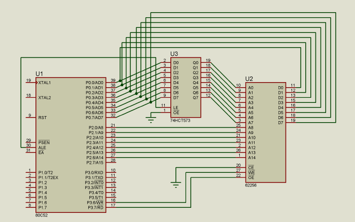
Because P0 is used as both the data bus and as the low byte of the address bus (usually called data and address multiplexing), an 8-bit latch is required to store the lower half of the address.
This circuit does that:

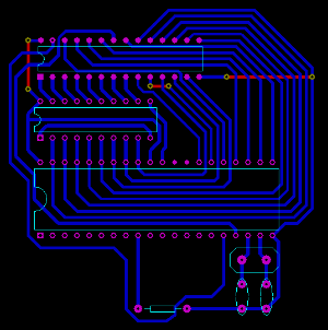
Because the memory allows random access, it doesn’t really matter if address bus pins are mixed up, as long as they are all connected the RAM access will work. The same thing happens with the data line. This only applies for RAMs, if it was an EEPROM or other memory that needs to be programmed before using it (for example a memory storing the program to execute) it wouldn’t really work, as the data would be mixed up and in the wrong position.
Leveraging that lets us do a PCB using a single layer, with only a few wire bridges, as shown by this image:

Download PCB, editable in Proteus
Optimized way of cleaning a buffer in external memory
Assuming we have a 1024 byte buffer (for example as a framebuffer for an external LCD), in external memory, at address 0, in an 8052 microcontroller running at 24 MHz, 2 MIPS.
The easier way to clean that buffer would be to use four loops, each one cleaning 256 bytes of the external memory.
    mov dptr, #0  ;Starting address of the buffer
    mov a, #0xAA  ;Value to set the buffer with

    mov r0, #0
lp1:movx @dptr, a
    inc dptr
    djnz r0, lp1

    mov r0, #0
lp2:movx @dptr, a
    inc dptr
    djnz r0, lp2

    mov r0, #0
lp3:movx @dptr, a
    inc dptr
    djnz r0, lp3

    mov r0, #0
lp4:movx @dptr, a
    inc dptr
    djnz r0, lp4
This solution takes 3076.5 microseconds (measured with Keil uVision simulator).
For some critical applications, this may be a bit too much, so optimizations can be made.
The first optimization would be to remove the four loops and replace it with just one:
    mov    dptr, #0
    mov a, #0xAA

    mov r0, #0
lp1:movx @dptr, a
    inc    dptr
    movx @dptr, a
    inc    dptr
    movx @dptr, a
    inc    dptr
    movx @dptr, a
    inc    dptr
    djnz r0, lp1
Besides reducing the code size, it also reduces the execution time, to 2307 microseconds, a 30% improvement.
In order to reduce it further, the movx @r0, a instruction, can be used, which does the same as DPTR but it only requires a 8 bit register, and uses P2 as the higher byte of the address.
	mov a, #0xAA
	mov r0, #0
lp1:
	mov p2, #0
	movx @r0, a
	inc p2
	movx @r0, a
	inc p2
	movx @r0, a
	inc p2
	movx @r0, a
	djnz r0, lp1
Now it only takes 1922 microseconds.
By unrolling the loop (reducing the frequency between djnzs by adding more instructions to modify the data) a time of 1858 microseconds (x2 unrolling) or 1826 microseconds (x4 unrolling) can be achieved.
For example, this method uses only 1603 microseconds, Almost half the time of the first one!
    mov a, #0xAA
    mov r0, #0
    mov p2, #0
lp1:
    movx @r0, a  ;P2 = 0
    inc p2

    movx @r0, a  ;P2 = 1
    inc p2

    movx @r0, a  ;P2 = 2
    inc p2

    movx @r0, a  ;P2 = 3
    dec r0

    movx @r0, a  ;P2 = 3
    dec p2

    movx @r0, a  ;P2 = 2
    dec p2

    movx @r0, a  ;P2 = 1
    dec p2

    movx @r0, a  ;P2 = 0

    djnz r0, lp1
In order to compare it and calculate an absolute efficiency, a simple analysis is the following: the movx instruction takes 1 microsecond, and each inc takes half a microsecond, so in order to be 100% efficient it would take 1536 microseconds to clean the buffer. Considering that this last method takes 1603 microseconds, we can say it’s 93% efficient, which is quite high for using just some simple unroll optimizations.
The idea of optimization is to find a balance between extra memory usage (code and data) and algorithm complexity and speed.