Alphanumeric LCDs based on HD44780
Most alphanumeric LCDs (often called smart LCDs, as they include a controller in the same board and don’t need a powerful CPU to use them) are part of an industrial standard designed for interfacing with embedded systems (mostly microcontrollers or microprocessors). They come in many different configurations, for example 8x1 (1 row, 8 characters per row), 16x2, 20x4, and even bigger ones are available.
These LCDs are designed to show text (and up to 8 custom-defined characters) so they are used in simple machines that don’t need to display complex information, such as printers, fax machines, copiers, etc. They can include a backlight, which can consist of LEDs or fluorescent tubes (in older models).
They often come with a 16 pin interface, with the following typical pinout:
- Ground
- VCC (3.3 o 5V)
- Contrast adjustment (VO)
- RS (Register selection: RS=0 means command, RS=1 means data)
- RW (Operation selection: RW=0 writes, RW=1 reads)
- Enable (activated in the falling edge)
- Bit[0..7] (Data bus)
- Optional: Backlight anode (+)
- Optional: Backlight cathode (-)
The LCDs can operate in both a 4-bit and an 8-bit mode. In the first one, bytes are sent divided into 4-bit nibbles, sending them first in the higher nibble of the data bus (Bit[4..7]). The commands in the 4-bit mode are the same ones, the only thing that changes is the initialization process.
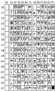
The internal ROM usually has every ASCII and sometimes Greek or Japanese characters. It’s possible to use up to 8 custom-defined characters (corresponding to ASCII positions 0 to 7) which are stored in volatile RAM.
A computer can easily control one of these LCDs, for example using the LCD Smartie program and a simple parallel port adapter.
To connect one of this LCDs to a microcontroller, this connection can be used:
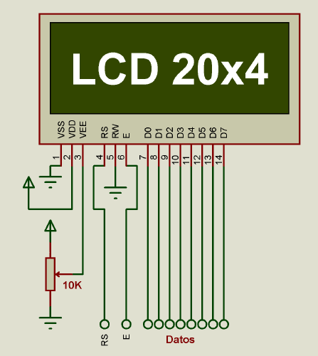
As the image shows, the contrast can be adjusted with a 10K potentiometer, in a resistive divider configuration. The RW pin can be grounded since most applications don’t need to read from the LCD. Data lines must be connected to a port of the microcontroller (keeping the same order). The other control lines should be connected as well.
Sending a command or data to the LCD:
- Set RS pin to 0 (command) or 1 (data)
- Set the data bus to the desired 8-bit value
- Do a pulse in E pin
- Wait until the instruction is executed (the time depends on which instruction was executed)
After turning on, the LCD’s controller does some internal tests, cleans its memory, which can take up to 20 milliseconds. That’s why a delay might be required, to ensure proper initialization of the controller of the LCD.
Important commands:
Erase screen
RS = 0, Data = 0000 0001, Time: 2 ms
Action: Erases the LCD, places the cursor in position 0
Turning ON/OFF the display
RS = 0, Data = 0000 1DCB, Time: 40 us
Actions:
- Turns on (D=1) or off (D=0) the LCD
- Turns on (C=1) or off (C=0) the cursor
- Turns on (B=1) or off (B=0) the blinking of the cursor
Function selection
RS = 0, Data = 001 BNF–, Time: 40 us Actions:
- Chooses 8-bit (B=1) or 4-bits (B=0) interface
- Chooses 2 line (N=1) or 1 line (N=0) - bigger displays need to use 2 line mode
- Chooses 5x8 (F=0) or 5x10 (F=1) characters (doesn’t do anything in most LCDs)
DD direction selection
RS = 0, Data = 1ADDRESS, Time: 40 us
Actions: Selects the address of the internal memory that will be affected when reading and writing.
The DD memory stores every character displayed on the screen. For instance, in a 20x4 LCD, the lines are in the following memory positions:
- Line 0: Position 0
- Line 1: Position 64
- Line 2: Position 20
- Line 3: Position 84
Write data
RS = 1, Data = ASCIICHAR, Time: 40 us
Action: Writes the specified data to the address previously set, and increments the internal pointer.
Init sequence (8 bits mode)
The full initialization sequence is the following:
- Wait 20 ms after power on
- Send command 0000 1110 (LCD on, cursor on, blinking off)
- Wait until the command completes (40 us)
- Send command 0000 0110 (text direction: right)
- Wait until the command completes (40 us)
- Send command 0011 1000 (8-bit bus, 4 lines, 5x8 font)
- Wait until the command completes (40 us)
After doing the init sequence, writing a character in an (x;y) position is as easy as doing the following:
- Calculating the correct memory position:
MemPos = LineStartAddress[y] + x - Send the command
(10000000 + MemPos)to move the internal pointer to that position - Wait until the command completes (40 us)
- Send the code of the ASCII character to be written as data
After doing that, the desired character will appear in the LCD, in the selected position. It’s possible to expand the software by storing x and y coordinates so that a long text can be split into two different lines.
Built-in characters are usually the following ones: