LED Matrix, methods to control
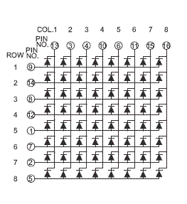
An LED matrix is often composed by LED diodes set up in this way:

The configuration is like the one used in diode ROMs, with the difference that it uses LEDs.
How to control it?
The process is quite simple
- Output in column port the output desired for the first row
- Turn on the first row
- Wait a short amount of time, in the order of milliseconds
- Turn off the first row
The process is then repeated with the second row, third row, and so on until it gets to the last one. The process then restarts with the first row.
This has to be done all the time, so it’s best done with a microcontroller. It’s possible to handle the matrix with standard digital logic, using counters and memories, but it’s too complicated and messy.
The time to wait depends on the LEDs and the desired refresh rate. This time, combined with the persistence of vision effect of the human vision allows the LED matrix to be seen as if every row was turned on, when it really isn’t. In most LED matrices this effect can be seen by moving fast the head or eyes, to see a delay effect in each row or column. It can also be seen in a video or photo camera if the shutter speed is faster than the refresh rate of the matrix.
A low refresh rate means that the display will blink too much, and might be bothering to look at. A value of 10ms per row (in an 8x8 matrix) seems to be good enough.
The resistors are needed to avoid burning the LEDs. It might be possible to use lower resistors than expected, since they are only on for 1/8 duty cycle. The datasheet should indicate the maximum peak current in a similar condition, to improve brightness when doing this type of scanning.
In a microcontroller, using an internal timer is a good method, since it allows for quite exact timings without needing to waste time in a delay. The main loop can also be used to do other tasks, and the interrupt routine can handle the matrix itself.