Introduction to PIC microcontrollers
In order to define a PIC microcontroller, we will first need to know what a microcontroller is. In broad strokes, it’s an integrated circuit that has most of the stuff a computer has:
- CPU: processes and executes every instruction. Their main parameters are the maximum speed it supports and the width of the data bus it has, which generally defines de width of the internal registers. In most microcontrollers, CPUs are orders of magnitude slower in comparison with typical PC CPUs, and typically 8 to 32 bits.
- Memory: holds both the program instructions as well as the data space that will be used by the program to store temporal data (RAM). Typically, microcontrollers have their program stored in an EEPROM/Flash memory.
- Peripherals:
- General purpose input/output ports (GPIO): they typically come in groups of 8 and are used to read and write external signals. They usually control external devices such as LEDs, relays, switches, or any other digital components.
- Analog inputs: most microcontrollers feature ADC converters that can be used to work with analog signals. Their main parameters are the maximum sampling speed and the resolution. Both parameters defines the maximum frequency of the signal that can be sampled, as well as the sensitivity and signal-to-noise ratio in the quantization process.
- Timers and counters: they are synchronic circuits that allow the microcontroller to count internal time (timer) or count external pulses (counters). Some of them can also be used to generated clock signals, measure frequency and period, generate a PWM signal, read a quadrature encoded signal, etc. Most of them have an interrupt line, which can interrupt the CPU when a certain event happens, for instance, when the timer overflows.
- Non volatile memories: some microcontrollers also feature internal EEPROM memory, usually used to store configuration data that needs to be preserved even if the energy gets removed. Also, some microcontrollers can self program their program memory.
- PWM module: basically generates a PWM signal, with different frequency and duty cycle according to the value set in different registers. It can be used to regulate motor speeds, do a digital to analog conversion, regulate the intensity of lights, make sounds, among other applications.
- Comparators: they are peripherals that allow for the comparison of two analog signals. On some microcontrollers, one of the signals can be generated internally by a voltage reference. The output result of the comparison is binary and can be read by the micro, and some even support generating interrupts when the comparison goes into one certain state.
- **Communication ports: ** most of the microcontrollers feature one or more UART/USARTs, which allow for easy communication between the microcontroller and external peripherals. Most of them support at least a serial (both synchronic and asynchronic) and some even support other protocols such as I2C, SPI, USB, Ethernet, among others.
The main advantage of microcontrollers over microprocessors is that they cost less, have lower power consumption and they don’t need much external circuitry in order to work. PIC microcontrollers are usually chosen because of their simple architecture, their low cost and great amount of code available in the web, as well as the great amount of tools to program them.
This article is oriented to low/middle tier PICs, mainly the 16F series. They can handle natively 8-bit data, and are based in a Harvard architecture: the memory used to store the program is separated from the memory used to store data.
To start with a small project with PIC, we need three main things:
- A program to compile code into instructions that the microcontroller understands (compiler/assembler)
- Components to try the circuits, or a simulator
- Some patience
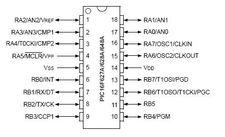
For instance, the PIC16F628A doesn’t have many peripherals, but it’s a nice choice to enter the world of microcontrollers. It has 2K of program memory, 224 bytes of RAM and 128 bytes of EEPROM memory.
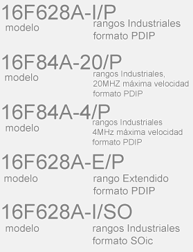
The models have different identification codes:
- First field: model
- Second field: Temperature and voltage range (I = industrial, E = extended)
- Third field (optional): Maximum supported speed (4/20/45) - measured in MHz
- Fourth field: Package format (ML = QFN, P = PDIP, SO = SOIC, SS = SSOP)
How to make a program for a microcontroller
There are three basic ways to do it: using C, using Basic and using Assembler
To compile the C code, the main used program is CCS, a C compiler for Microchip microcontrollers, which is fast and quite good. The only issue is that it’s not free. The typical program used for testing microcontrollers is blinking an LED, since it can be used to validate that the environment, compiler and programmer are all working fine.
In C, the program used is quite easy to understand:
#include <16f628a.h> //Which microcontroller we have
#use delay(clock=4000000) //To use the delay routines, we need to tell the compiler we're running at 4MHz

void main(){
	while(true){
		output_high(PIN_A0); //Prendemos la línea A0
		delay_ms(500); //Esperamos medio segundo
		output_low(PIN_A0); //Apagamos la línea A0
		delay_ms(500); //Esperamos medio segundo
	}
}
The compiled C program used 52 Words
To use Basic, a simple IDE that features a basic compiler is called PIC SIMULATOR IDE, it’s paid as well. The code used was the following:
main:
	High PORTA.0
	WaitMs 500
	Low PORTA.0
	WaitMs 500
	Goto main
The compiled program used 66 Words
To program it in Assembly, MPLAB IDE can be used, as well as gputils (a free and open alternative). The assembled program used less program memory than both before, but is harder to maintain and to understand.
How to transfer the HEX file to the microcontroller
A PIC programmer (sometimes called burner) is needed. One of the cheaper ones is called JDM, and connects to the PC using the serial port. There are also multiple official programmers, such as the PICKit series, as well as clones of those. Special caution is needed before programming, since there are some fuses that can make the microcontroller not programmable anymore.
Some typically used programs are IC-Prog, Pony Prog, WinPic800, PicPGM. Most of them support different types of programmers.
There are also solutions that use Zero-Insertion Force (ZIF) sockets, to avoid breaking the fragile IC pins after several insertion/removal cycles.
Also, most microcontrollers allow for In-Circuit Programming, which allows for reprogramming the microcontroller without removing it from the circuit. This needs five connections that connect it to the programmer
These lines are the ones called Vpp, Vss, Vdd, Pgd and Pgc. If those lines were used by external circuitry, protection components may be needed, since they get driven as outputs.
A simple PIC test schematic is the following:
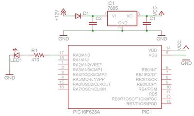
Components:
- D1 is a rectifier diode, avoids burning the microcontroller if the voltage is reversed.
- IC1 regulates the input voltage to 5 v, needed by the microcontroller to correctly run. C1 and C2 act as filters and smooth the output voltage.
- The PIC is connected to the 5 v supply as well as ground, and from pin 17 (bit 0 of port A, RA0) a LED and a resistor are connected to ground. The resistor limits the current flowing through the LED, protecting it and the microcontroller.