Input/output port expansion
In some projects, more inputs or outputs than the microcontroller can handle are needed. These are some solutions:
- Use a PPI IC like the old 8255 (slow and big), parallel interface, uses 10 extra pins, and provides three extra 8-bit I/O ports.
- Use an I2C expander, like PCF8575 (hard to find, possibly expensive)
- Use 74xxx logic (cheap, easy to program, and high availability)
This article will focus on the third option, and mainly for single directional pins
Expanding outputs
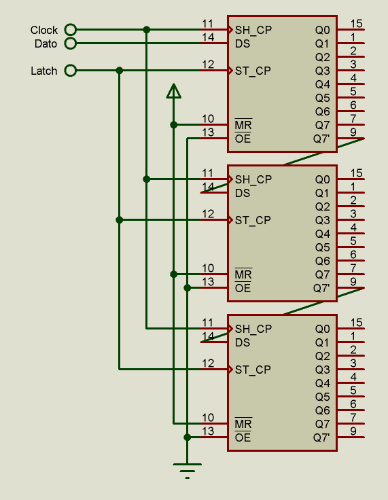
The two main ICs are 74x164 (no latch) and 74x595 (with output latches). Multiple ICs can be cascaded, so each one of them adds 8 extra outputs.
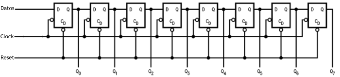
Internally they have multiple shift registers (type D flip-flops chained), so the data can be pushed from one side and the 8 bits can be accessed in parallel.
They have three control pins:
- Clock: Given a pulse, the data shifts through the flip flips, and a new bit enters from the leftmost FF.
- Data: They receive the new value to add to the first flip flop.
- Reset: When a pulse is applied, all the bits go to a 0 state
Some ICs, like 74x595 have an extra pin, that when pulsed makes the data transfer to the output. That means that the changes are done to internal flip-flops, and when activating the latch pin, the bits appear in the device pins.
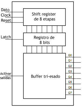
If the outputs shouldn’t show glitches while data is changing (for instance, lights, relays, or motors), a shift register with latch should be used.
Writing a value to a shift register is easy:
- For each bit: (starting by the rightmost one)
- Place the bit in the data pin
- Make a pulse in the clock pin
- Make a pulse in the Latch pin (if applicable) to change the state of the outputs to the one desired.
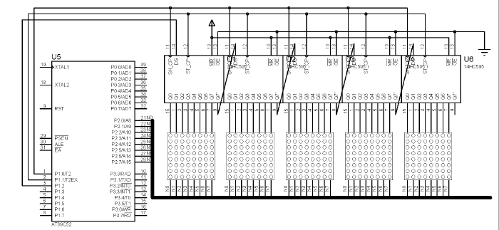
This image shows how to put multiple shift registers in a chain:
A typical application of this circuit is to drive big LED matrices, using only a few pins of a microcontroller:
Expanding inputs
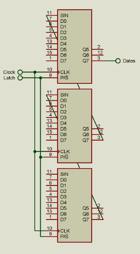
In order to expand inputs, ICs such as 4014 can be used. They work in a similar fashion, with the difference that the shift registers are parallel input and serial output. The sequence to read the bits is the following:
- Make a pulse in the Latch pin
- For each bit[i]: (starting from the right)
- Read Data pin, store in bit[i]
- Make a pulse in the clock pin
- Increment i
This image shows how to expand inputs using multiple chained shift registers.