RF tools
These are some RF tools I put together. They are not calibrated lab instruments, but they help when measuring equipment, filters, and RF outputs.
The general idea was to make small pieces with SMA connectors that are easy to insert into a measurement setup with a VNA, wattmeter, or receiver/analyzer.
Dummy load
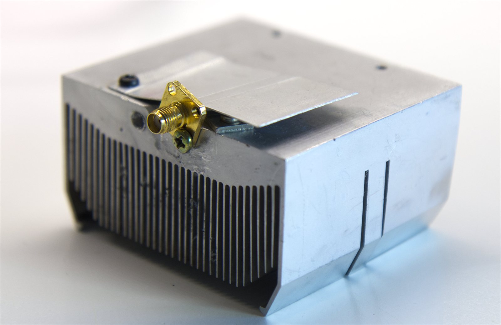
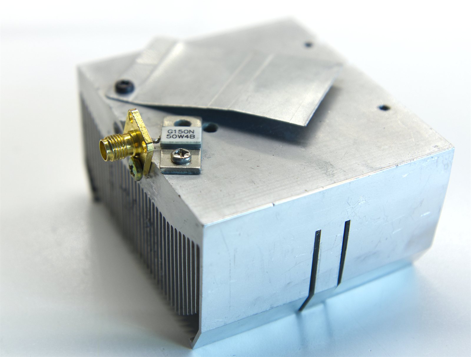
The dummy load is made with a G150N 50W4B resistor (50 ohms, 150 W) mounted on an old CPU heatsink. The resistor is screwed to the aluminum and connected directly to an SMA connector, keeping the path as short as possible so it still works well at high frequencies.
The heatsink is not very large, so it is not suitable for dissipating continuous power, but it is useful for measuring low-power transmitters or doing quick tests.
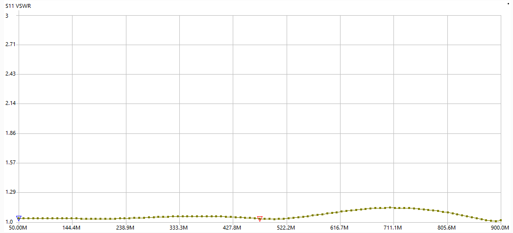
It has a VSWR less than 1.15 up to 900 MHz.
-40 dB RF tap
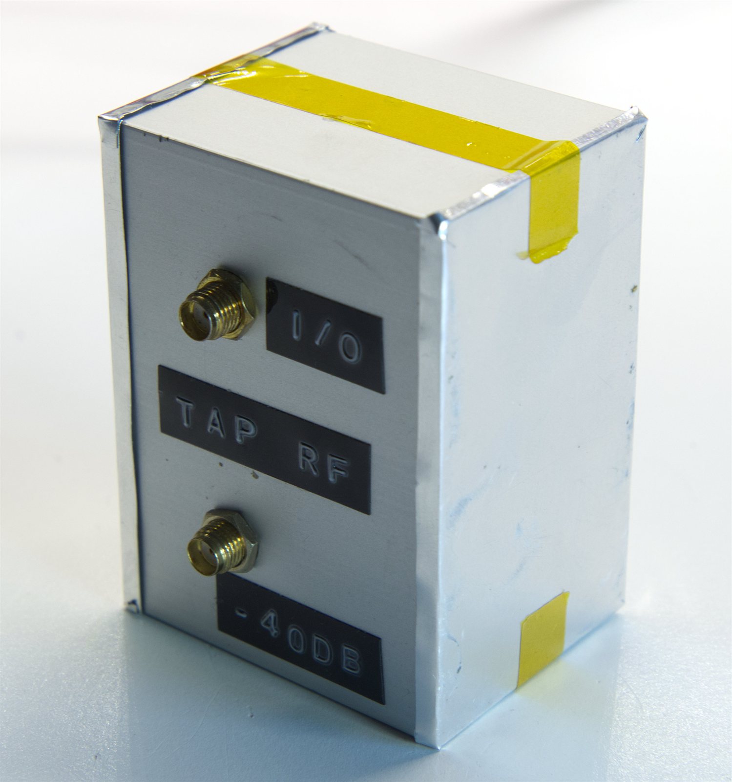
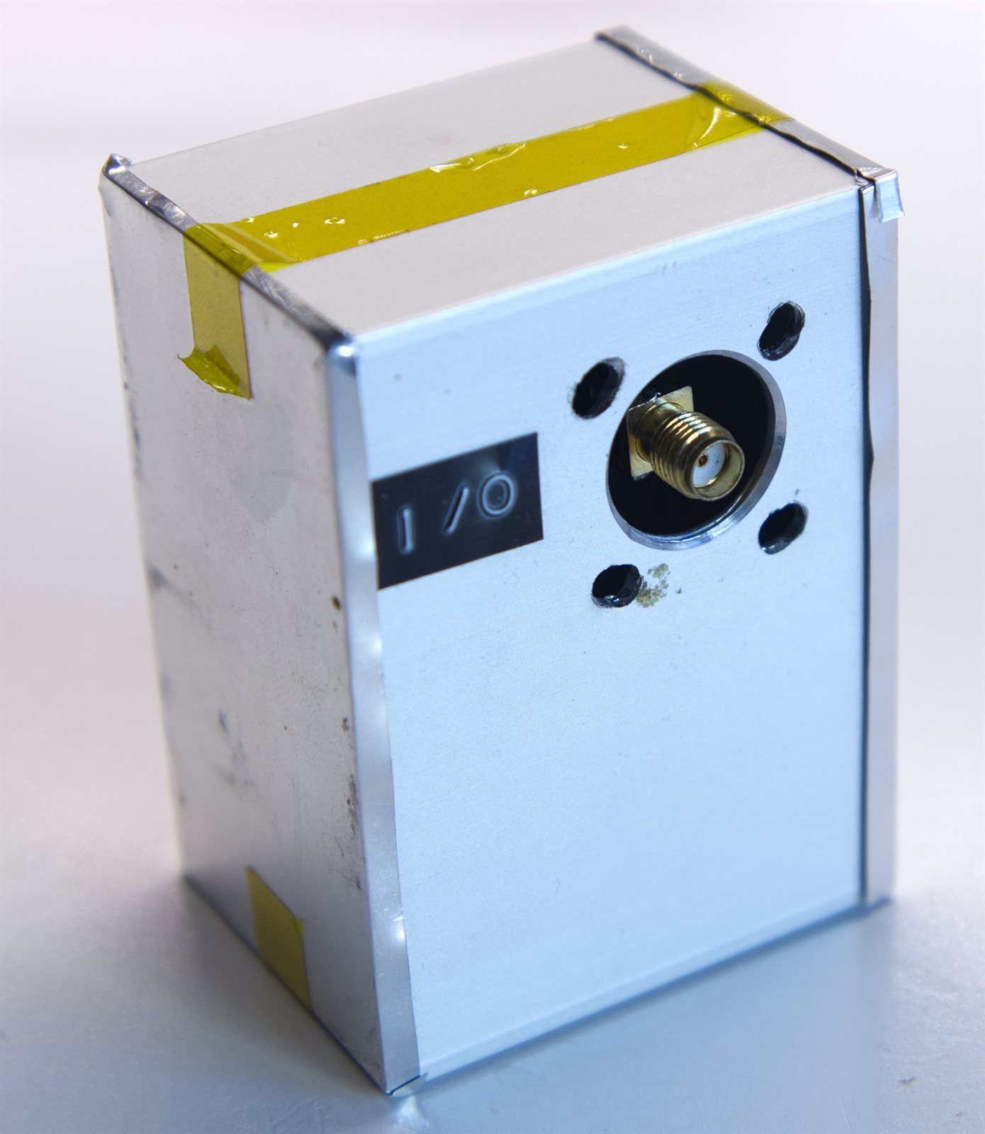
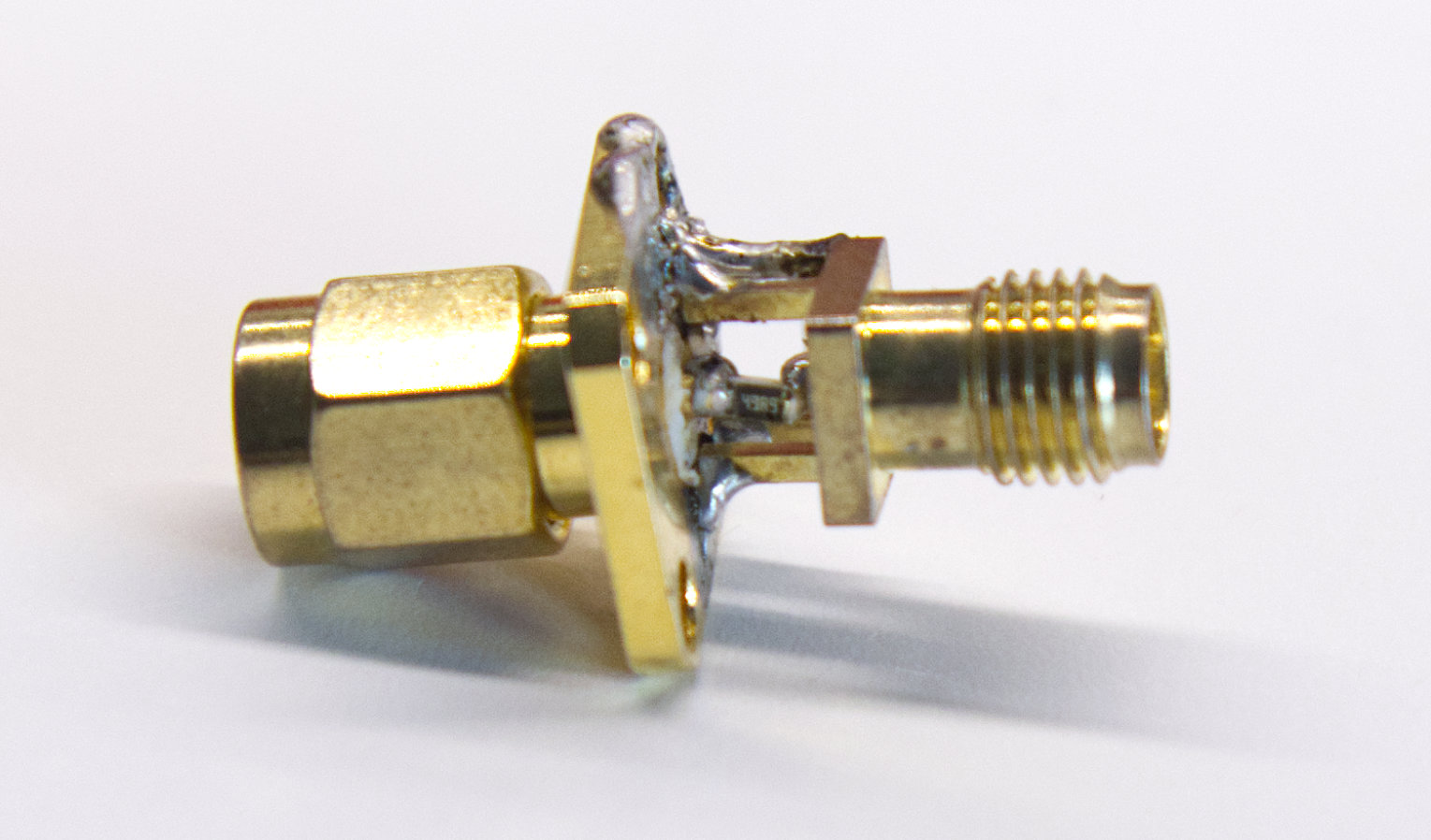
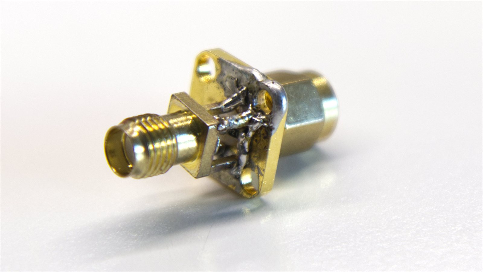
The RF tap has two main connectors for the line that passes straight through, plus a third sampling connector that provides approximately -40 dB relative to the signal on the main line.
For example, if 10 W are passing through the line, the sample port ideally outputs 1 mW. That makes it very useful for observing a transmission with sensitive equipment, such as a spectrum analyzer, without connecting it directly to the transmitter output. In other words, it can be used to inspect a transmitter’s output power without burning the instrument.
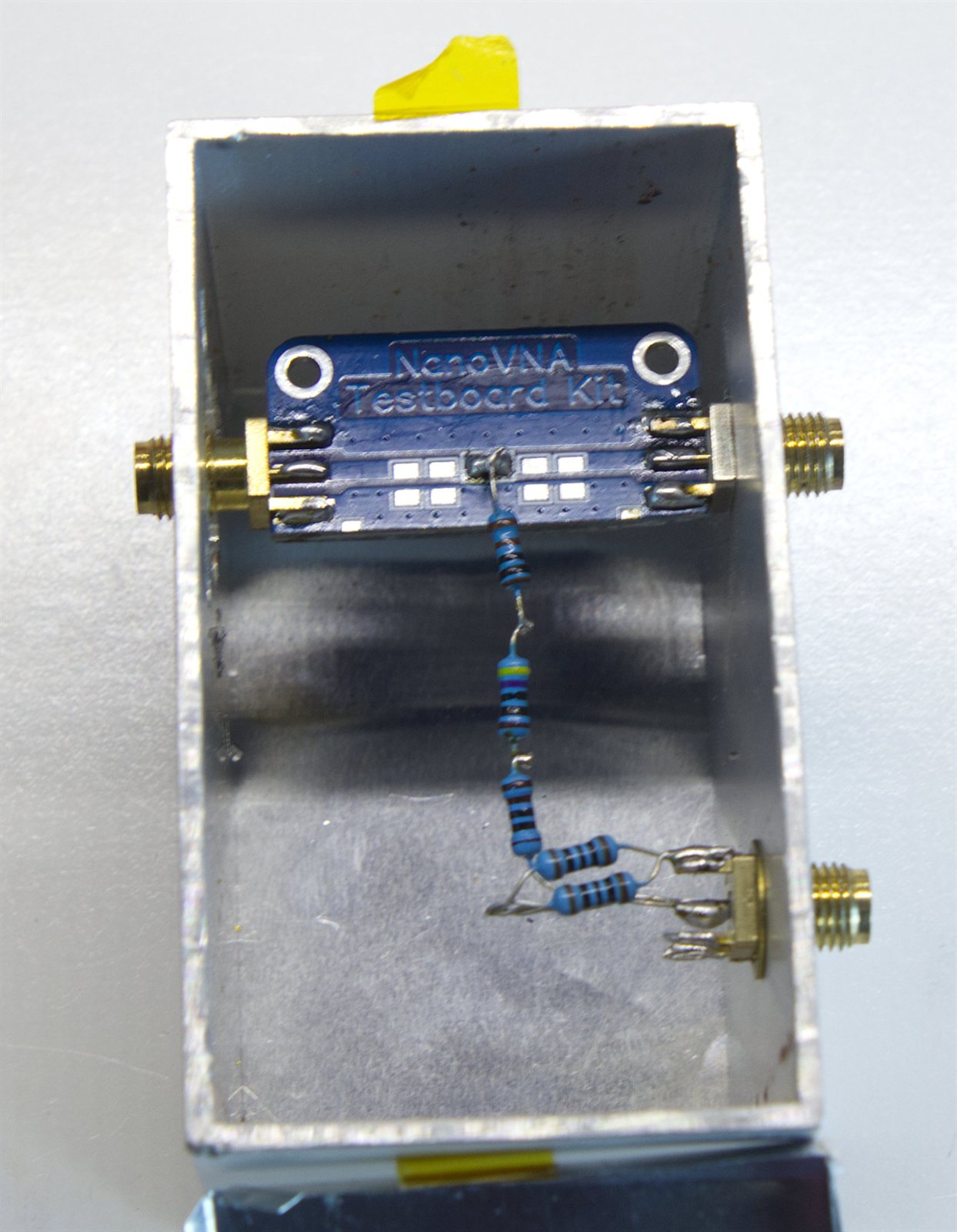
Internally it uses a piece of a NanoVNA testboard kit as the through line, mounted inside an aluminum enclosure. The tap toward the third SMA connector is made with discrete resistors.
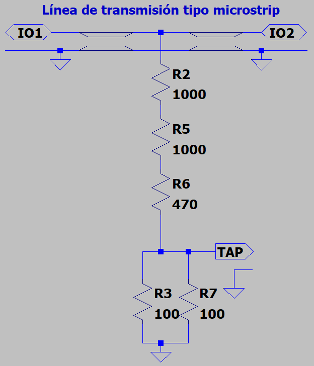
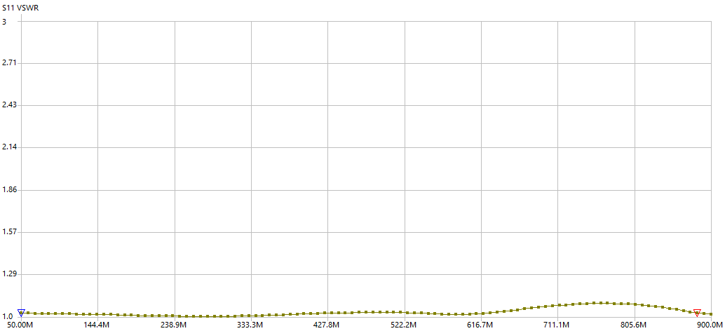
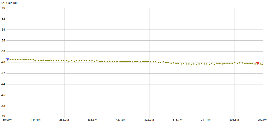
It works well up to 1 GHz (as can be seen, it has a VSWR less than 1.5), and the -40 dB attenuation is fairly stable across the whole range, so it can also be used to measure harmonics of HF, VHF and UHF signals without trouble.
Mini 7.7 dB attenuator
This mini attenuator adds around 7.7 dB of attenuation. It is a low-power attenuator built directly between SMA connectors with three SMD resistors.
It can be used at the output of the tap. If a device is still delivering too much power for the instrument even through the -40 dB output, this attenuator reduces it further.
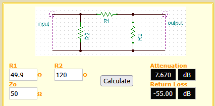
The calculations were done with this calculator, trying different combinations of the resistor values I had available to minimize return loss. It is a pi attenuator: https://leleivre.com/rf_pipad.html
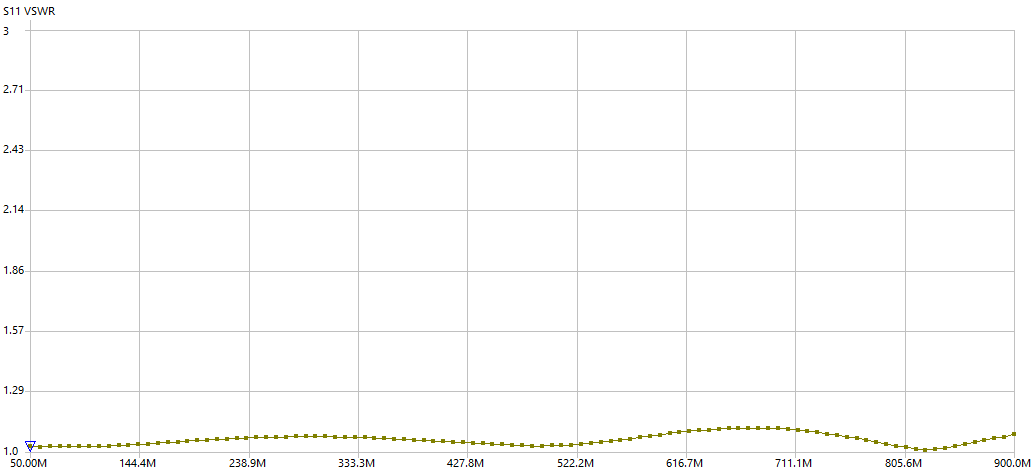
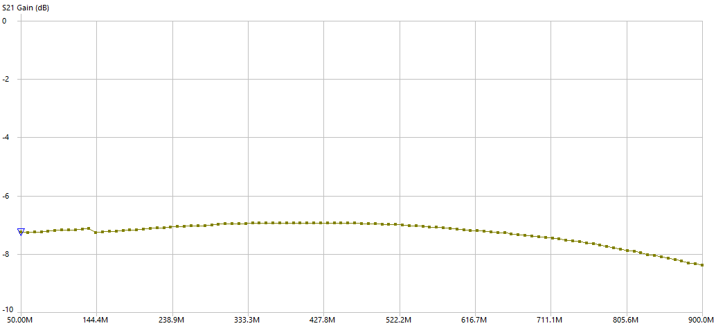
It can be seen that it has a VSWR less than 1.5 up to 1 GHz, and that the attenuation is more stable than expected across the same range.
Female VNA calibration standards
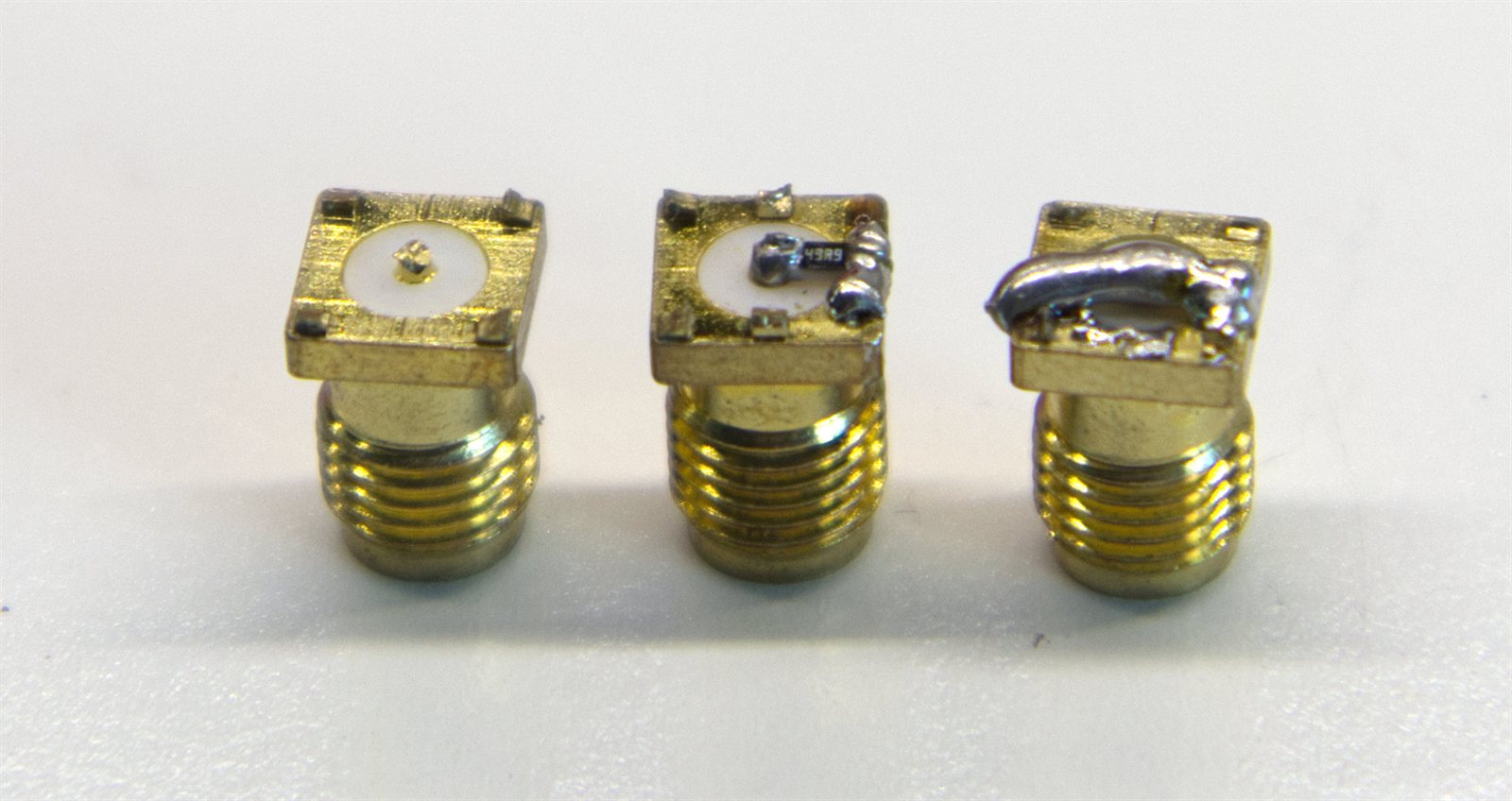
This is a set of female SMA calibration standards for the VNA: open, load, and short. It is especially practical because filters or small boards under test often have male SMA connectors, while the classic NanoVNA kit has the opposite calibration standards, which introduces measurement errors.
With these standards, the reference plane can be moved directly to the female connector where the device under test will be plugged in.
They are easy to build:
- The short is a female SMA connector with a direct solder bridge between the center pin and the body.
- The load is a female SMA connector with a 50-ohm SMD resistor (49.9 ohms in my case, which does not change much) connected between the center pin and the body.
- The open is a female SMA connector with the center pin cut.