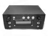
Muscular electrostimulator (2011)
The following information is given without any warranty, I’m not responsible for possible accidents. The project involves high voltages, which can lead to severe accidents and even death.
Code and editable schematics for the project can be found here.
This electrostimulator is formed by three main blocks: a voltage booster, a controller, and a high voltage control stage.
Voltage booster
The booster is built using a flyback type inverter:
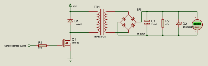
The transformer used is a 220V-6V, connected in such a way that outputs more voltage in the output. The Zener diode limits the voltage to around 100V DC.
Controller
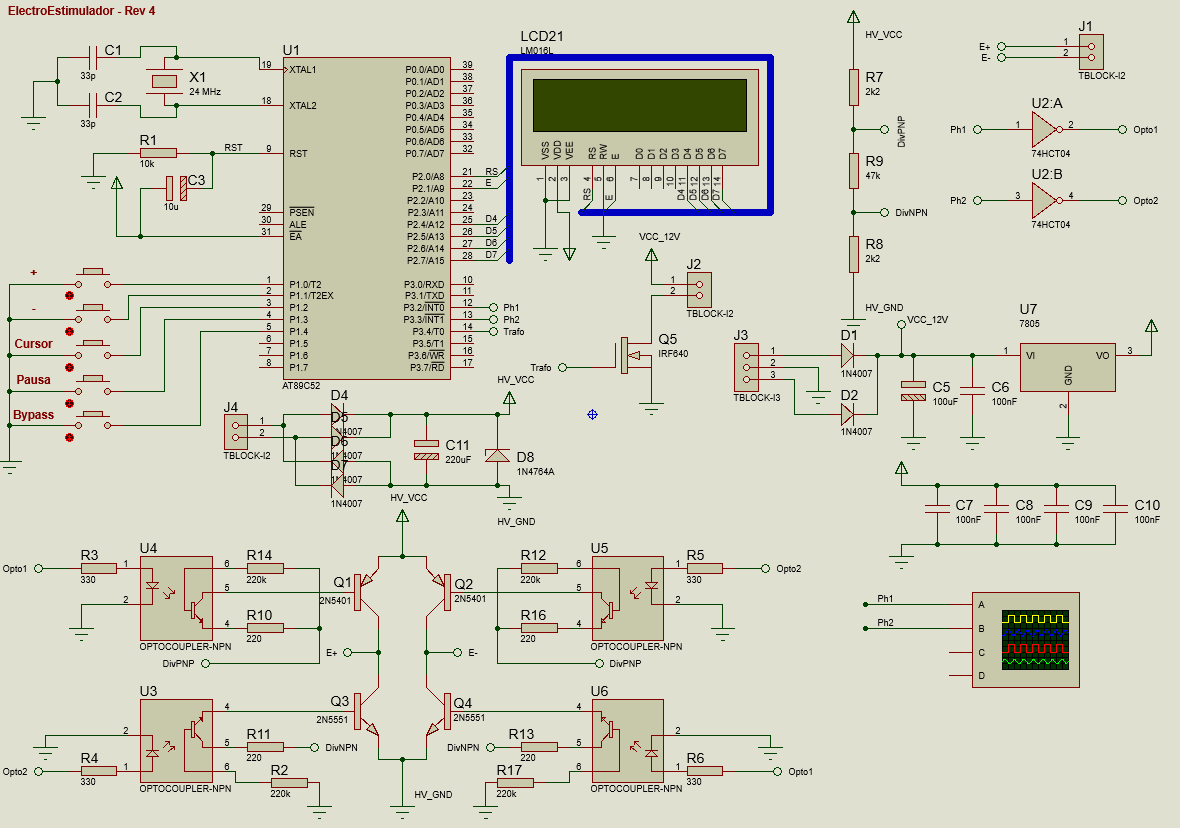
A controller was designed using the AT89S52 microcontroller. It generates the different waveforms according to the selected program. It also has a small user interface to change modes. The different waveforms are generated via Pulse density modulation.
High voltage control
To handle the high voltage outputs from the microcontroller, four high speed optocouplers were used, as well as two pairs of 2N5401 and 2N5551 transistors to create an H-bridge.
The electrodes used are the following:
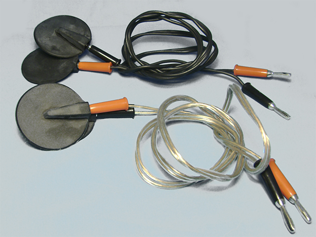
They get connected to the stimulator using banana-banana wires. To improve conductivity and require less voltage, applying a small amount of neutral gel (conductive fluid) is suggested.
A series potentiometer (50 kohm) is used to regulate the output voltage and intensity that gets applied to the muscle.