Matrix keyboards, microcontroller interface
Making a keyboard with 4-pin buttons (also known as tactile switches) is very easy, especially using the fact that two pairs of the 4-pins are connected internally, so it’s possible to use a single board PCB without needing extra wire jumps.
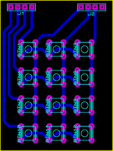
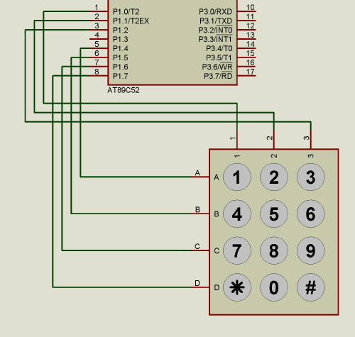
The easiest way to read the keyboard status from a microcontroller is the following: it can be connected to a single 8-bit I/O port, using the low nibble for columns and the high nibble for rows.
A sample code may be the following:
- Every sample time ms (10 o 20 milliseconds typically)
- Activate the first column, deactivate the other ones
- If any row is active, the pressed key is
idxRow*3 - Activate the second column, deactivate the other ones
- If any row is active, the pressed key is
idxRow*3+1 - Activate the third column, deactivate the other ones
- If any row is active, the pressed key is
idxRow*3+2
For more complex applications, it is possible to add a gate to detect when any key is presses. This can be used to let the microcontroller enter a sleep mode (low power consumption), and create an external interrupt when any key is pressed.
If the detection of multiple simultaneous keys is needed, it’s possible to add a small diode in series with each button. If the diode is not added, when pressing two or more keys (especially diagonally adjacent keys) the detection of ghost keys might happen. Most computer keyboards don’t have these diodes, but the keys are arranged in such a way that the probability of detecting ghost keys is low. For instance, the arrow keys, WASD, adjacent letters are usually in the same row, so it’s possible to detect two of them regardless of the state of the other keys.