Four channel RF remote control, using HT12D/E
These simple circuits can be used for a high number of applications, from RC cars and ships to garage door openers, car alarms, data acquisition, robotics, and others.
The radiofrequency section is based on the cheap transmitter/receiver pair WenShing TWS-BS-X, and RWS-X-X which modulate using ASK (more information of the transmitters and the receivers). They usually cost less than 2 U$D each, and with a good antenna and tuning, they might work with distances of around 50 meters.
The encoding and decoding is based on the HT12E (encoder) and HT12D (decoder) ICs, that allow up to 4-bit data and 8-bit address (allowing up to 256 devices on the same frequency, provided they don’t attempt to transmit at the same time)
Transmission
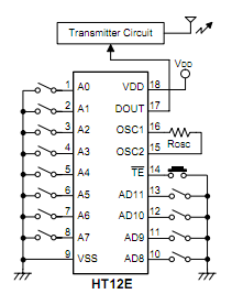
The pins 1 through 8 select the address (which needs to be the same in the transmitter and the receptor to receive the data), pins 10 through 13 are the data to be transmitted, pin 14 controls the transmission (if low it transmits, can be tied to ground so it’s a continuous transmission). Pins 15 and 16 need to have a 1 Megohm resistor to generate the internal clock signal. Pin 17 is the output pin so it must be connected to the transmitter module.
Reception
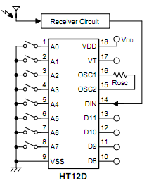
Again, pins 1 through 8 select the address, pins 10 to 13 are the received data (they can be connected to loads or LEDs as long as the current is less than 5mA). Pin 14 must be connected to the receiver module output. Pins 15 and 16 need to be connected to a 47 Kohm resistor, to generate the internal clock signal. Pin 17 states if the reception was correct or not.
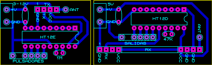
Download editable PCBs for Proteus
A similar circuit, but using HT12A and HT12F can be used for communications via infrared or LASER. This ICs comes with an internal modulator of 38KHz, similar to those used in standard infrared remote controls.